Resistors in Series and Parallel

Practice!
| Practice 7.1.1 |
|---|
In this example, this circuit has two resistors, with R1 > R2. Which of the two resistors dissipates the larger amount of power? (Remember that the power dissipated in a resistor can be calculated with either 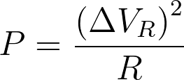 or or  ) ) |
Now we will look at a similar circuit but we will replace the resistors with light bulbs. Light bulbs are also resistors, but when you buy a light bulb you aren’t told what the resistance is. Instead the light bulb package has a power rating on it.
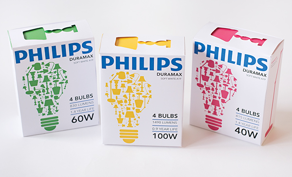
These power ratings are determined by assuming the light bulb is connected to a power source of 120 V (which is the average voltage of a typical household electrical outlet). We can use the power rating and this 120-V voltage to calculate the resistance of the light bulb:


So the light bulb with a power rating of 100 W has a resistance of 144 Ω. The 40 W light bulb will have a different resistance:
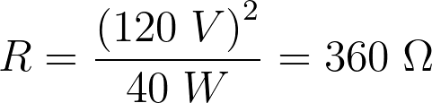
In the example, the voltage across the bulbs will not be 120 V, so the bulbs will not dissipate energy at the labeled power rating, but the resistance of the bulb can be calculated using the method above.
| Practice 7.1.2 |
|---|
A 60 W light bulb and a 100 W light bulb are placed one after the other in a circuit. The battery’s emf is large enough that both bulbs are glowing. 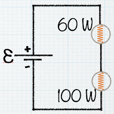 Which one glows more brightly? |
| Practice 7.1.3 |
|---|
This circuit has two resistors, with R1 > R2. 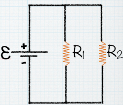 Which of the two resistors dissipates the larger amount of power? |
| Practice 7.1.4 |
|---|
A 60 W light bulb and a 100 W light bulb are placed one after the other in a circuit. The battery’s emf is large enough that both bulbs are glowing. 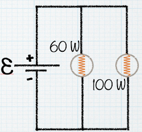 Which one glows more brightly? |
| Practice 7.1.5 |
|---|
What is the current through the 5 Ω resistor?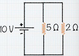 |
| Practice 7.1.6 |
|---|
| What is the current through the 2 Ω resistor? |
| Pause & Predict 6.2.1 |
|---|
| What is the voltage drop across R2, the 20-Ω resistor? |
| Pause & Predict 6.2.2 |
|---|
| What is the equivalent resistance of these three resistors in parallel? |
Practice!
| Practice 7.1.7 |
|---|
| Four resistors (R1 = 150 Ω, R2 = 250 Ω, R3 = 350 Ω, R4 = 450 Ω) are connected in series with a 12-V battery. What is the current that flows through the 250-Ω resistor? |
| Practice 7.1.8 |
|---|
| Four resistors (R1 = 150 Ω, R2 = 250 Ω, R3 = 350 Ω, R4 = 450 Ω) are connected in parallel with a 12-V battery. What is the equivalent resistance of the circuit? |
| Practice 7.1.9 |
|---|
| Four resistors (R1 = 150 Ω, R2 = 250 Ω, R3 = 350 Ω, R4 = 450 Ω) are connected in parallel with a 12-V battery. What is the current flowing out of the battery in this circuit? |
More Resistor Circuits

Discuss!
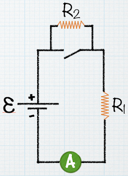
With the switch closed, there is no current in R2 because the current has an alternate zero-resistance path through the switch. There is current in R1 and this current is measured with the ammeter (a device for measuring current) at the bottom of the circuit. If the switch is opened, there is current in R2. What happens to the reading on the ammeter when the switch is opened?
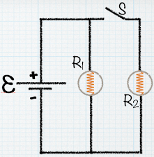
Two identical light bulbs are represented by the resistors R1 and R2 (R1 = R2). The switch S is initially open. I(before) is the current before the switch is closed and I(after) is the current after the switch is closed.
(a) What happens to the total current after the switch is closed? In other words, what is I(after) in terms of I(before)?
(b) If switch S is closed, what happens to the brightness of the bulb R1?

The three light bulbs in the circuit all have the same resistance of 1 Ω. Compare the brightness of bulb B to the brightness of bulb A. (brightness is proportional to power)
