Module 5 Class Activities
Electric Circuits I
I. Lighting a bulb
A. Work individually for this part. Sketch how you could light a small flashlight bulb using a battery, a single wire, and a light bulb. (You may use this simulation to get a more “hands on” feeling of the system, if you’d like.)
Show the details of the bulb and battery in your sketch and explain your reasoning.
If it is not possible to light a bulb with a battery and one wire, explain why not.
B. Compare your reasoning with that of your partners. You don’t have to agree with one another, but discuss your answers until you understand each others’ reasoning.
C. If you have a battery, light bulb, and wire, go ahead and use them. If you don’t have these supplies, use this simulation. Connect the battery, light bulb, and wires in as many ways as you can. For each arrangement, note whether the bulb lights or does not light.
Sketching each arrangement will help you to be systematic. Divide your sketches into two categories: arrangements that allow the light bulb to light up, and arrangements that do not allow the light bulb to light up.
D. Find at least four different arrangements that light the bulb. How are they similar? How are they different from arrangements in which the bulb fails to light?
II. Building a model for battery and bulb circuits
A. If you have a light bulb, examine it closely, perhaps with a magnifying glass. If you do not have a light bulb, you can use this image for reference:

Where do the wires on either side of the filament originate? Sketch what you find.
B. Light a bulb using a battery and two wires.
- Observe and record the brightness of the bulb when objects made out of various materials are inserted into the circuit. (Try copper, paper, iron, steel, plastic, glass, aluminum, rubber, and whatever else you have handy. If you are using the simulation, the scrolling menu on the left provides random objects that you can insert into the circuit.) Does the bulb continue to glow brightly or does it go out?
- Classify your materials into different categories according to their effect on the bulb. What do most of the objects that let the bulb light have in common?
An object that allows the bulb to glow brightly is called a conductor. An object that makes the bulb go out is called an insulator. Some objects fall between these two categories.
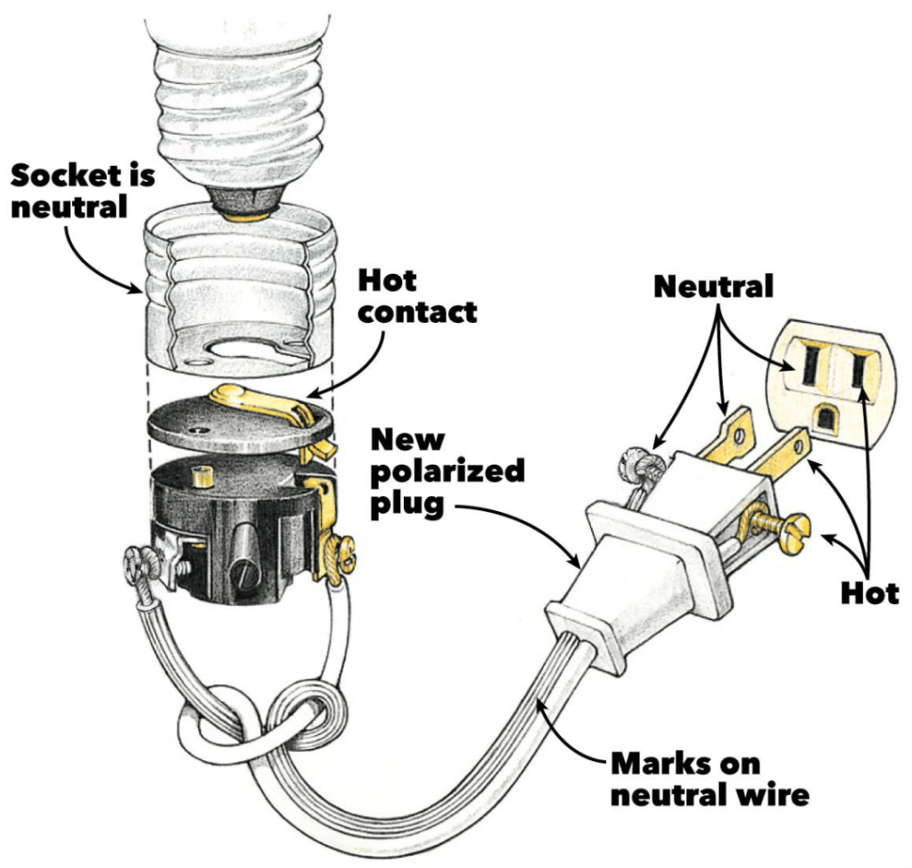
C. For convenience, light bulbs are usually placed in sockets. Carefully examine a socket. Identify the conducting and insulating parts. Determine which of the conducting parts are connected to one another.
D. What’s your thinking about how battery-bulb circuits work? What do you think is going on in arrangements that light the bulb? What is it about arrangements that don’t light the bulb that prevent it from lighting? (This is one of the most important questions in the tutorial.)
Check in with an LA or instructor before proceeding.
There is more than one valid way to imagine what’s happening in a circuit. One way of thinking, which we will explore in some detail in this class, includes the following assumptions:
- There is a flow in a complete circuit from one terminal of the battery, through the rest of the circuit, back to the other terminal of the battery, through the battery and back around the circuit.
- For identical bulbs, the brightness of a bulb is an indicator of the amount of flow through the circuit.
These assumptions are consistent with our observations. However, we don’t have direct evidence for either of them, and we have by no means ruled out other ways of thinking that involve quite different ideas. (There are, in fact, whole other ways of thinking about circuits that are equally correct.)
We use the term “electric current” to refer to the flow described above.
III. Circuit diagrams
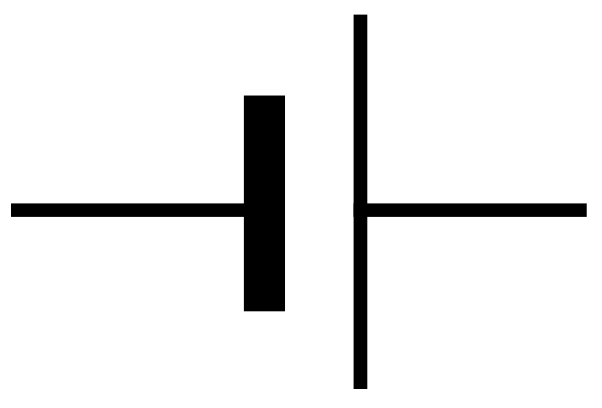
Circuit diagrams let us represent a circuit on paper by using symbols for the batteries and bulbs instead of drawing pictures. The symbol for a battery is shown at right. The ends of a battery are called terminals. The long line represents the positive terminal of the battery (knob end), and the short line represents the negative terminal (flat end).
The knob and screw base of a bulb are also called terminals. The symbol for a bulb is shown at right. Note that although the symbol for a battery shows it has two different terminals, the symbol for a bulb shows no difference between the two terminals. Nevertheless, one side of the bulb symbol represents the tip of the bulb, and the other represents the screw threads on the side.

The symbol for a switch is:

The representation used for wires is more complicated than the simple symbols for batteries, bulbs, or switches. As we have seen, contact through a conductor is just the same electrically as direct contact. Direct contact and connection by a wire are therefore represented by the same symbol: a line or a group of connected lines. In each case below, the diagrams show that points A and B are electrically connected.

Individual parts of a circuit, such as batteries, bulbs, and switches, are often called circuit elements. From a circuit diagram, we cannot tell whether two elements of a circuit are far apart and connected by a wire or whether the elements are actually touching. This means that the diagram for a circuit may look quite different from its actual physical appearance. On the other hand, this kind of diagram is particularly useful in analyzing circuits because it focuses on electrical connections rather than the physical arrangement of the circuit.
We have found that a bulb will light only if there is a complete circuit: a closed loop from one end of the battery, through the bulb, and back to the other end of the battery. A circuit diagram that shows a bulb connected to a battery to form a complete circuit is shown in the accompanying diagram. The wires from the battery are often referred to as positive and negative leads.

A. In which of the circuits below will the bulb light?
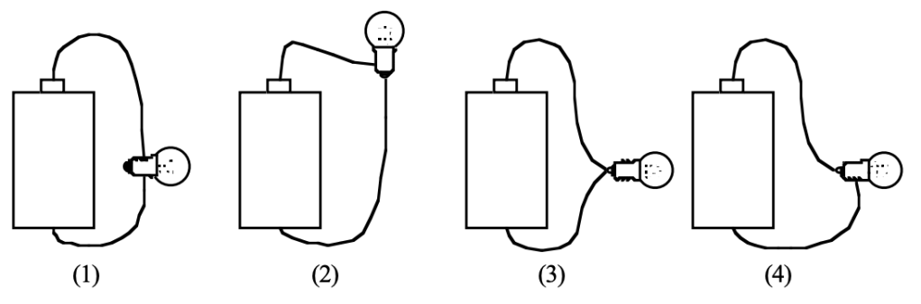
B. Draw standard circuit diagrams for the four arrangements of battery, bulb, and wires shown above. Which of them have identical circuit diagrams?
C. What does a line mean in a circuit diagram? Why do the symbols for batteries, bulbs, and switches have a line on each side?
D. Why does it make sense that the symbol for a bulb shows no difference between the two terminals?
IV. Circuits with more than one bulb
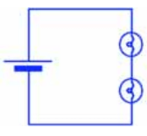
A. Work individually for this part. Imagine a two-bulb circuit with the bulbs connected one after the other as shown. Don’t set it up yet. Predict how the brightness of the two bulbs will compare to the brightness of an identical bulb in a single-bulb circuit. (Two bulbs connected one after the other are said to be in series.)
B. Compare your reasoning with that of your partners. Again, you don’t have to agree with one another, but discuss your answers until you understand each others’ reasoning.
C. Obtain the equipment (or simulation), set up the circuit, and record your observations.
- How does the current through the bulb in a single-bulb circuit compare with the current through the same bulb when it is connected in series with a second bulb?
- What does this imply about the current through the battery?
- Compare the brightness of the two bulbs in the two-bulb circuit with each other. What can you conclude from this observation about the amount of current through each bulb?
- It’s possible that some effects you observe might be due to manufacturing irregularities in the bulbs – that so-called “identical” bulbs might not, in fact, be quite identical. How might you test whether any differences are due to manufacturing irregularities?
D. On the basis of your observations and the reasoning you used above, respond to the following questions:
- Is current “used up” in the first bulb, or is the amount of the flow the same through both bulbs?
- Can you tell the direction of the flow through the circuit?
- How does the amount of the flow through the battery in a single-bulb circuit compare with the flow through the battery in a circuit with two bulbs connected in series?
