Electromotive Force

6.1 Electromotive Force
Learning Objectives
By the end of this section, you will be able to:
- Describe the electromotive force (emf) and the internal resistance of a battery
- Explain the basic operation of a battery
Electromotive Force, emf
Voltage devices create a potential difference and can supply current if connected to a resistance. The potential difference creates an electric field that exerts force on charges, causing current. We thus use the name electromotive force, abbreviated emf. The symbol we use for emf is a curly E:  .
.
Emf is not a force at all; it is a special type of potential difference. To be precise, the electromotive force (emf) is the potential difference of a source when no current is flowing. The units of emf are volts.
Batteries: an example of an emf device

Zinc ions (+ charged) get pulled off by chemistry (we won’t go into the details of that here, though) into the acid bath, leaving behind a residual negative charge on the Zn rod (this is called a terminal, or an electrode). Meanwhile, electrons (- charged) are pulled off the carbon rod into the acid bath, leaving a residual + charge on the C terminal. That means the carbon side is now at a higher potential, VA > VB. This potential builds up, but if VA gets too high, the acid can’t pull electrons off any more (the electrostatic attraction of electrons back onto the + carbon rod will equal the chemical attraction of the electrons into the acid). So you reach an equilibrium with ΔV = VAB = VA – VB = some fixed value depending on the chemicals.
People usually drop the Δ, and just talk about “V”, the battery’s voltage. (Too bad, remember they really mean the difference in voltage between the two electrodes.) Some people will call this the emf of the battery, using a curly , emf = = work/charge, the electrical potential difference created.
If there’s no circuit, the two terminals have some potential difference across them, but no current flows. If you connect something across them, current will flow, but the IDEAL battery maintains a constant voltage between the terminals. The emf device provides energy to the charges moving around the circuit.
In circuit diagrams, we use this symbol:

for batteries, or in general for sources of emf. The “+” and “-“ are often left off: the longer line always represents the “+” side. It’s a little like the symbol for capacitors, except the lines are different lengths. Capacitors and batteries have some common aspects, but they are still very different. Capacitors don’t spontaneously build up a ΔV, like batteries do, and they don’t always maintain the same value of ΔV.
You might expect that the “+” charges at the top of the carbon electrode would want to go over to the “-” electrode. They are attracted to each other. The +’s would drop in energy, ΔU = qΔV: they’d like that, like rolling down a hill. They can’t go through the acid, though: the chemical reactions are stopping them. But what if you let them go some other way, outside of the acid?
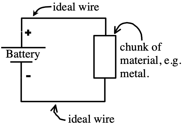
Now we’ve provided an outside path, a conducting path, or circuit, for charges to flow from the + to – sides of the battery like they want to. There is a current flowing continuously through the circuit. This is a simple electric circuit. This is NOT like discharging a capacitor (where the flow is quick, and then stops when the capacitor is discharged). The battery keeps maintaining a constant potential difference, and the current is continuous.
Terminal Voltage
Real batteries always have some small, unavoidable internal resistance “r” in them. We can usually neglect it, but in real life (like if you short circuit a battery) the current is large but never infinite due to the small but finite “r”. What I mean by short circuit a battery is to connect the + terminal directly to the – terminal with a wire. If you do this, the battery will get really hot. Where do you think that heat comes from? There’s a lot of friction going on inside that battery and this is the same friction that we call resistance.
In this picture, the battery is represented by the dashed square:

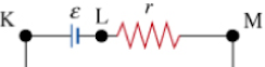
Inside the battery is the source of emf and the internal resistance (r). It would be something like this:

The points (a) and (b) are the terminals of the battery. If you wanted to measure the voltage of this battery, you would put your voltmeter probes at (a) and (b). This voltage you measure — called the terminal voltage, because it’s measured at the terminals of the battery — is less than the emf because there is a small voltage drop across the internal resistance:

where  is the voltage drop across the internal resistance.

Practice!
| Practice 6.1.1 |
|---|
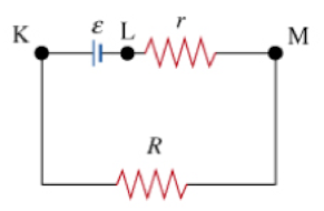 For the circuit shown where r is an internal resistance and R is an external resistor, which potential difference corresponds to the terminal voltage of the battery? |
| Practice 6.1.2 |
|---|
 A battery has emf = 12.0 V and internal resistance = 3.00 Ω. A voltmeter is connected to the terminals of the battery; the battery is not connected to any other external circuit elements. What is the reading of the voltmeter? |
| Practice 6.1.3 |
|---|
A battery has emf = 12.0 V and internal resistance r = 3.00 Ω. A 21.0-Ω resistor is connected to the terminals of the battery. What is the current through the battery? |
| Practice 6.1.4 |
|---|
A battery has emf = 12.0 V and internal resistance r = 3.00 Ω. A 21.0-Ω resistor is connected to the terminals of the battery. What is the current through the 21.0-Ω resistor? |
| Practice 6.1.5 |
|---|
A battery has emf = 12.0 V and internal resistance r = 3.00 Ω. A 21.0-Ω resistor is connected to the terminals of the battery. What is the potential difference across the 21.0-Ω resistor? |
| Practice 6.1.6 |
|---|
A battery has emf = 12.0 V and internal resistance r = 3.00 Ω. A 21.0-Ω resistor is connected to the terminals of the battery. What is the terminal voltage of the battery connected to the 21.0-Ω resistor? |
