Resistors in Series and Parallel

6.2 Resistors in Series and Parallel
Learning Objectives
By the end of this section, you will be able to:
- Define the term equivalent resistance
- Calculate the equivalent resistance of resistors connected in series
- Calculate the equivalent resistance of resistors connected in parallel
Many real world electronic devices are just collections of wires, resistors, capacitors, and batteries, forming circuits that do something (flashlights, toasters, blow dryers, radios, amplifiers, …) It’s important to understand (and predict) the currents and voltages in such circuits.
Resistors in Series
Resistors are in series whenever the current must flow through devices sequentially. In this figure, the total amount of current  is the current that is pumped through the battery and it’s the same current that must flow through R1, R2, and R3. So these three resistors are wired in series. The current that goes through one must go through the next one. What goes in must come out — which is conservation of charge. This is not an approximation of any kind, it’s exactly true.
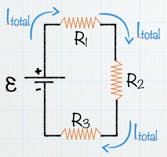
Let’s use the voltage loop rule and add up all the changes in voltage, starting at the battery and going around the circuit in the same direction as the current:


If we replaced these three resistors with one equivalent resistor:

The voltage loop rule equation would come out to be:

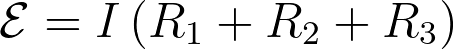
so when you compare the two loop rule equations for the equivalent circuits, you get:

When resistors are wired in series in a circuit, the resistance adds to get a bigger resistance. So the current drawn will be less the more resistors you have in series.

Practice!
| Practice 6.2.1 |
|---|
In this example, this circuit has two resistors, with R1 > R2. Which of the two resistors dissipates the larger amount of power? (Remember that the power dissipated in a resistor can be calculated with either 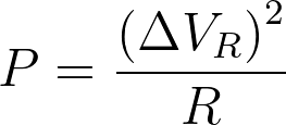 or or  ) ) |
Now we will look at a similar circuit but we will replace the resistors with light bulbs. Light bulbs are also resistors, but when you buy a light bulb you aren’t told what the resistance is. Instead the light bulb package has a power rating on it.

These power ratings are determined by assuming the light bulb is connected to a power source of 120 V (which is the average voltage of a typical household electrical outlet). We can use the power rating and this 120-V voltage to calculate the resistance of the light bulb:


So the light bulb with a power rating of 100 W has a resistance of 144 Ω. The 40 W light bulb will have a different resistance:
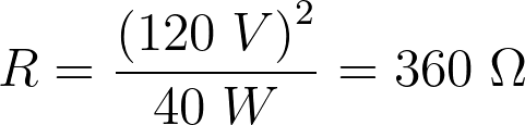
In the example, the voltage across the bulbs will not be 120 V, so the bulbs will not dissipate energy at the labeled power rating, but the resistance of the bulb can be calculated using the method above.
| Practice 6.2.2 |
|---|
A 60 W light bulb and a 100 W light bulb are placed one after the other in a circuit. The battery’s emf is large enough that both bulbs are glowing. 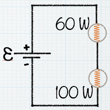 Which one glows more brightly? |
Resistors in Parallel
Resistors are in parallel when each resistor is connected directly to the voltage source by wires having negligible resistance. Each resistor thus has the full voltage of the source applied to it. The amount of current that flows through one resistor is not necessarily the same as the current that flows through another resistor when they are wired in parallel. In this circuit, the total amount of current that is pumped through the battery is . Some of that total current will flow through R1, some through R2, and the rest through R3. Since charge is conserved, what we can say is  .
.
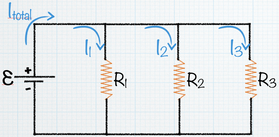
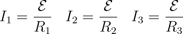
We can use Ohm’s law to find the amount of current that flows through each resistor in the parallel circuit. Because each resistor is directly connected to the power source, the voltage across each resistor will be equal to the voltage of the battery. Then we get
If we replaced these three resistors with one equivalent resistor,
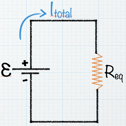
the current through this equivalent resistor would be

What we can do is relate the total current in each circuit to get

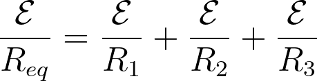
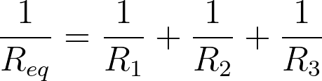
and since the emf is the same in each term, we can find a way to calculate the equivalent resistance when resistors are wired in parallel:
Practice!
| Practice 6.2.3 |
|---|
This circuit has two resistors, with R1 > R2. 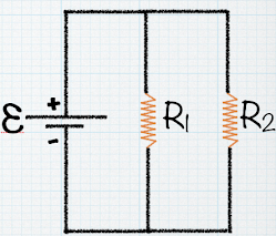 Which of the two resistors dissipates the larger amount of power? |
| Practice 6.2.4 |
|---|
A 60 W light bulb and a 100 W light bulb are placed one after the other in a circuit. The battery’s emf is large enough that both bulbs are glowing. 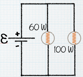 Which one glows more brightly? |
| Practice 6.2.5 |
|---|
What is the current through the 5 Ω resistor?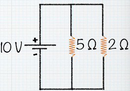 |
| Practice 6.2.6 |
|---|
| What is the current through the 2 Ω resistor? |
| Pause & Predict 6.2.1 |
|---|
| What is the voltage drop across R2, the 20-Ω resistor? |
| Pause & Predict 6.2.2 |
|---|
| What is the equivalent resistance of these three resistors in parallel? |
Practice!
| Practice 6.2.7 |
|---|
| Four resistors (R1 = 150 Ω, R2 = 250 Ω, R3 = 350 Ω, R4 = 450 Ω) are connected in series with a 12-V battery. What is the current that flows through the 250-Ω resistor? |
| Practice 6.2.8 |
|---|
| Four resistors (R1 = 150 Ω, R2 = 250 Ω, R3 = 350 Ω, R4 = 450 Ω) are connected in parallel with a 12-V battery. What is the equivalent resistance of the circuit? |
| Practice 6.2.9 |
|---|
| Four resistors (R1 = 150 Ω, R2 = 250 Ω, R3 = 350 Ω, R4 = 450 Ω) are connected in parallel with a 12-V battery. What is the current flowing out of the battery in this circuit? |
More Resistor Circuits

Discuss!
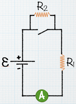
With the switch closed, there is no current in R2 because the current has an alternate zero-resistance path through the switch. There is current in R1 and this current is measured with the ammeter (a device for measuring current) at the bottom of the circuit. If the switch is opened, there is current in R2. What happens to the reading on the ammeter when the switch is opened?
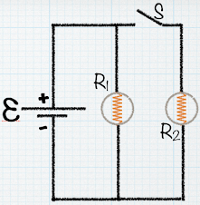
Two identical light bulbs are represented by the resistors R1 and R2 (R1 = R2). The switch S is initially open. I(before) is the current before the switch is closed and I(after) is the current after the switch is closed.
(a) What happens to the total current after the switch is closed? In other words, what is I(after) in terms of I(before)?
(b) If switch S is closed, what happens to the brightness of the bulb R1?

The three light bulbs in the circuit all have the same resistance of 1 Ω. Compare the brightness of bulb B to the brightness of bulb A. (brightness is proportional to power)
