PHYS 2212 Module 6 Self Assessment Practice Problems
Module 6 Self Assessment Practice Problems
6.1
The circuit shown in the figure contains two batteries, each with an emf and an internal resistance, and two resistors.
(a) Find the magnitude of the current in the circuit.
(b) Find the direction of the current in the circuit.
(c) Find the terminal voltage Vab of the 16.0 V battery.
Answer: (a) 0.47 A (b) counterclockwise (c) 15.2 V
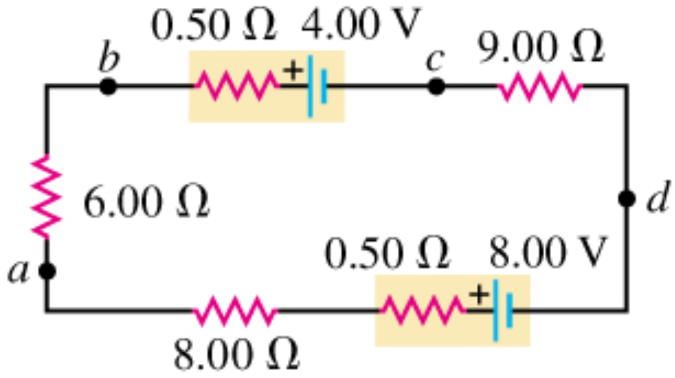
6.2
(a) What is the potential difference Vad in the circuit of the figure?
(b) What is the terminal voltage of the 4.00-V battery?
(c) A battery with emf 10.30 V and internal resistance 0.50 Ω is inserted in the circuit at d, with its negative terminal connected to the negative terminal of the 8.00-V battery. What is the difference of potential Vbc between the terminals of the 4.00-V battery now?
Answer: (a) 6.64 V (b) 4.09 V (c) 3.87 V
6.3
Electric fish generate current with biological cells called electroplaques, which are physiological emf devices. The electroplaques in the South American eel are arranged in 140 rows, each row stretching horizontally along the body and each containing 5000 electroplaques. Each electroplaque has an emf of 0.15 V and internal resistance of 0.25 Ω. If the water surrounding the fish had resistance of 800 Ω, how much current can the eel produce in water from near its head to near its tail?
Answer: 0.93 A
6.4
Three identical resistors are connected in series. When a certain potential difference is applied across the combination, the total power dissipated is 41.0 W. What power would be dissipated if the three resistors were connected in parallel across the same potential difference?
Answer: 369 W
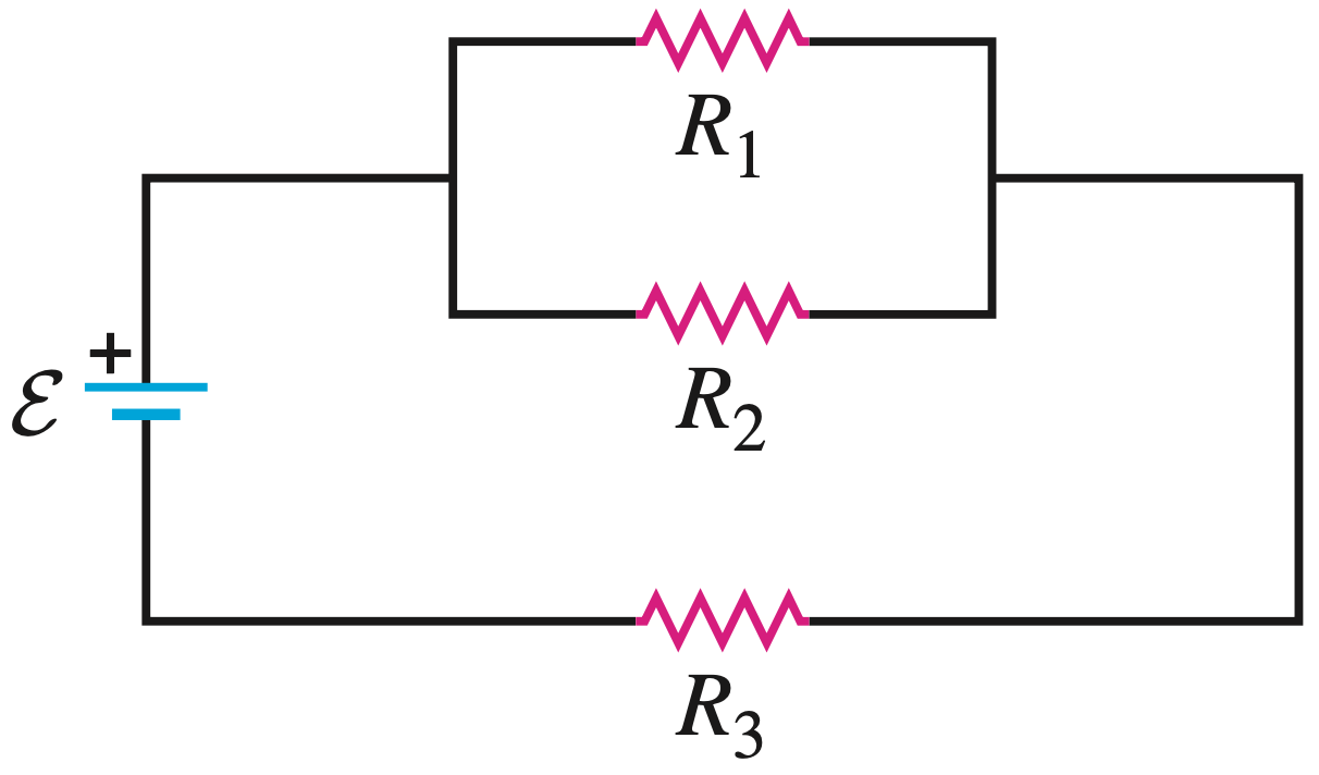
6.5
In the figure, R1 = 3.00 Ω, R2 = 6.00 Ω, and R3 = 5.00 Ω. The battery has negligible internal resistance. The current I2 through R2 is 4.00 A.
(a) What are the currents I1 and I3?
(b) What is the emf of the battery?
Answer: (a) 8 A, 12 A (b) 84 V
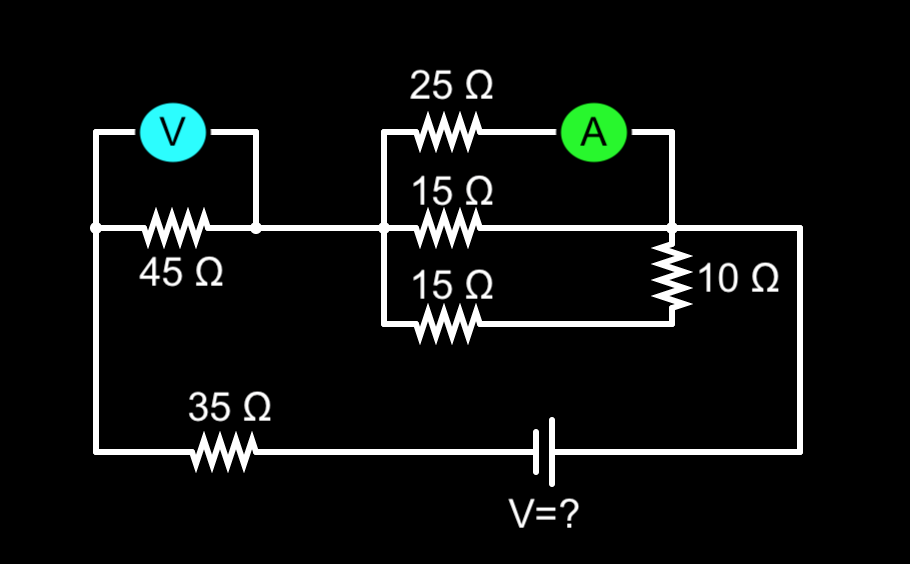
6.6
For the circuit shown, the battery has no appreciable internal resistance, and the ammeter reads 1.25 A.
(a) What does the voltmeter read?
(b) What is the voltage of the battery?
Answer: (a) 206 V (b) 398 V
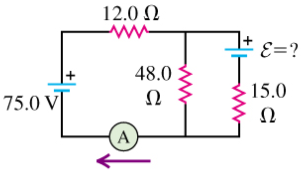
6.7
In the circuit shown in the figure, both batteries have insignificant internal resistance and the idealized ammeter reads 1.40 A in the direction shown.
(a) Find the emf of the battery.
(b) Is the polarity shown correct? Explain.
Answer: (a) 55 V (b) Yes
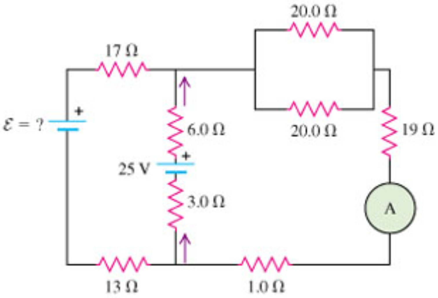
6.8
In the circuit shown in the figure, the 6.0 Ω resistor is consuming energy at a rate of 21.0 J/s when the current through it flows as shown.
(a) Find the current through the ammeter A.
(b) What are the polarity and emf of the battery, assuming it has negligible internal resistance?
Answer: (a) 0.27 A (b) 40 V, polarity reversed from that shown in the figure
6.9
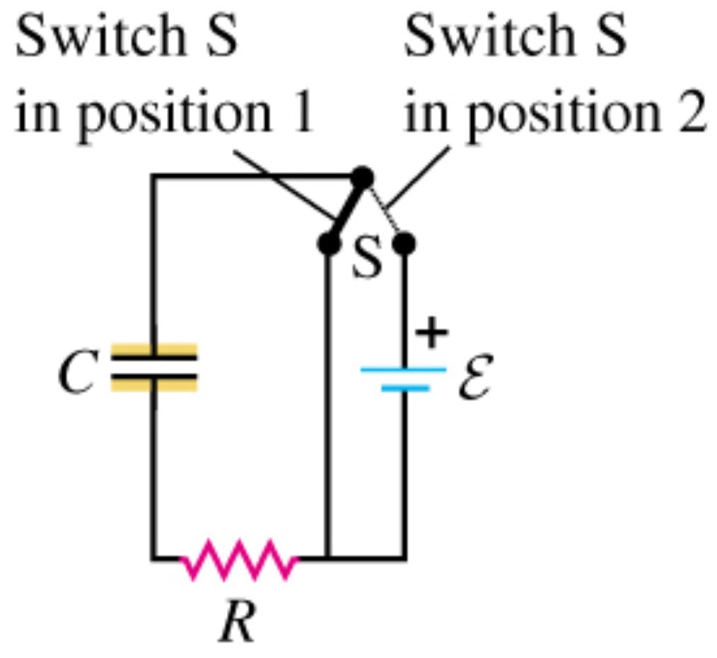
In the circuit shown in the figure, C = 5.90 µF, = 28.0 V, and the emf has negligible resistance. Initially the capacitor is uncharged and the switch S is in position 1. The switch is then moved to position 2, so that the capacitor begins to charge.
(a) What will be the charge on the capacitor a long time after the switch is moved to position 2?
(b) After the switch has been in position 2 for 3.00 ms, the charge on the capacitor is measured to be 110 µC. What is the value of the resistance R?
(c) How long after the switch is moved to position 2 will the charge on the capacitor be equal to 99.0% of the final value found in part (a)?
Answer: (a) 165 µC (b) 463 Ω (c) 12.6 ms
6.10
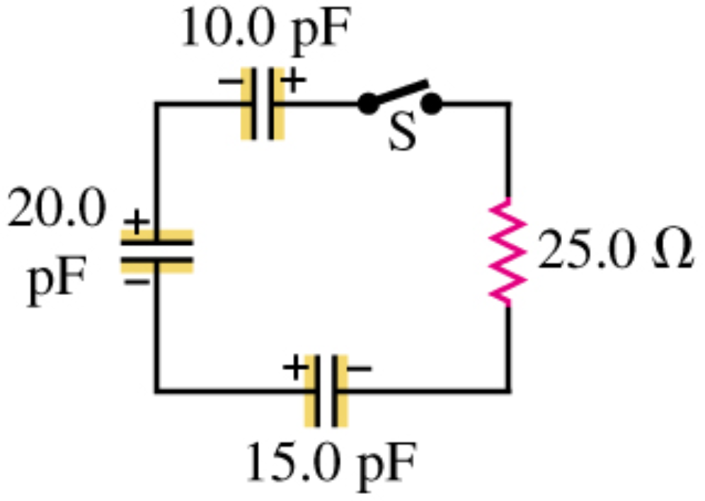
In the circuit shown in the figure, each capacitor initially has a charge of magnitude 3.60 nC on its plates. After the switch S is closed, what will be the current in the circuit at the instant that the capacitors have lost 80.0% of their initial stored energy?

 = 28.0 V, and the emf has negligible resistance. Initially the capacitor is uncharged and the switch S is in position 1. The switch is then moved to position 2, so that the capacitor begins to charge.