Module 7 Class Activities
Magnetic Fields and Forces
I. Investigate interactions of magnets and the space surrounding them
A. In the following video experiment, notice the markings on the ends of the bar magnets. (We used magnets that are marked with red (N) and white (S), but you may find other combinations such as brown (N) and white (S), red (N) and blue (S) and more.)
If you have some magnets, go ahead and recreate the experiment for yourself.
- Describe your observations and record the patterns you found.
- What other objects can interact at a distance in a similar way to magnets? What are the similarities and differences between these interactions and interactions of magnets?
B. In the following video experiment, the compass was placed on a table near the magnet and moved on the table around the magnet.
If you have a compass and a magnet, go ahead and recreate the experiment for yourself.
- Draw pictures of the compass needle orientations for the locations marked with points in the figure below.
- What are the patterns in the orientations of the compass needle?
- What can you say about the space surrounding the magnet (based on the behavior of the compass needle)?

Check in with an LA or instructor before proceeding.
II. Apply knowledge of magnets and compasses to explain a new phenomenon
In the following video experiment, the experimenter placed a sheet of white paper over the magnets and sprinkled iron filings on the sheet. A magnified image of the filings is pasted below.
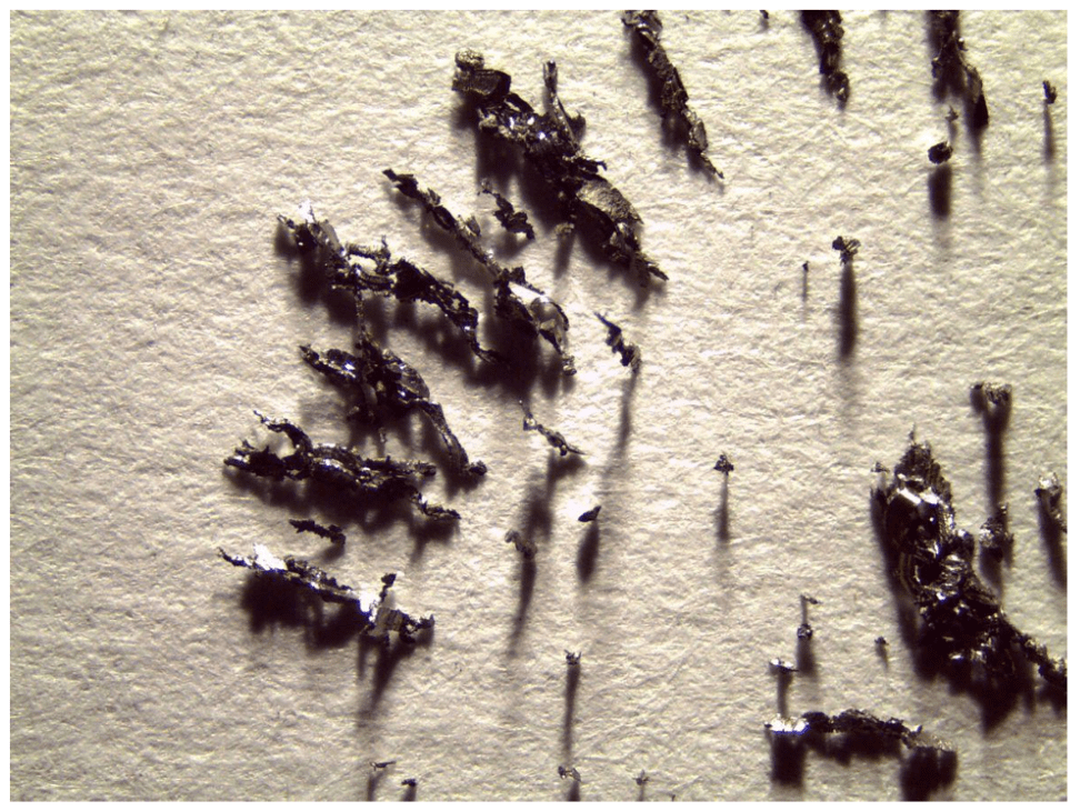
- Draw what happens to the filings for several different arrangements of the bar magnets.
- Explain why the fillings might arrange the way they do.
III. Investigate magnetic properties of a current carrying wire
A. In the following set of video experiments, we investigated whether current carrying wires produce magnetic fields.
- Why are both compasses oriented the same way before the current is turned on in the circuit? What is their orientation? Watch carefully to find N and S of the compasses.
- What can you say about the orientations of the compasses after the current is turned on in the first experiment? Do they turn in the same direction? Opposite?
- How does the direction of each change in the second experiment?
- What can you say about the magnetic field of the current-carrying wire based on these two experiments?
- Notice that the compass needles are not exactly perpendicular to the current carrying wire. Why could that be? (Hint: think of the magnetic field of Earth.)
Check in with an LA or instructor before proceeding.
IV. Observational experiment to relate the magnetic force, magnetic field, and current in a wire.
The goal of this experiment is to invent a rule that relates the directions of the magnetic force  , the directions of
  , and the directions of the current I in the wire.
A current-carrying wire is placed between the poles of an electromagnet. The direction of the  field lines produced by the magnet , is shown in the figure.

- Invent a rule that relates the directions of the magnetic force , the directions of , and the directions of the current I in the wire.
- Does your rule account for the outcomes of the experiments in the following video? Explain.
Link to video: https://mediaplayer.pearsoncmg.com/assets/_frames.true/secs-experiment-video-42
V. Testing the rule
Brainstorm about how you can use the equipment below to test the rule you developed for the direction of the force exerted by the magnetic field on a current-carrying wire. Using the set-up below, how do you expect the scale to respond when you turn on the power supply?
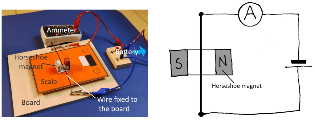
- Consider the available equipment and how you could use it to test the right-hand rule. Write down your potential experiments. Think ahead about what you will measure and how you will measure it.
- Describe the experimental procedure you have chosen. The description should contain a labeled sketch of your experimental set-up, an outline of what you plan to do, what you will measure, and how you will measure it.
- Use the hypothesis you are testing to make a qualitative prediction for your particular experiment. Show the reasoning used to make the prediction, including force diagrams as appropriate.
- Watch the following video of the experiment we conducted:
- Does it support or reject the rule for the force that you invented in Part IV? How do you know?
VI. Observational experiment to invent a rule for the magnitude of the magnetic force that the field exerts on a current carrying wire
The table below provides data concerning the magnitude of the magnetic force  exerted on a segment of a current-carrying wire by an external magnetic field as the following quantities are changed: (1) the magnitude of the external magnetic field , (2) the magnitude of the electric current I, (3) the length of the segment of the current-carrying wire L, and (4) the direction of the electric current relative to the direction of the magnetic field.
| Magnitude of the magnetic field (T) | Current in the wire I (A) | Length of the wire L (m) | Angle between current direction and field | Magnitude of the magnetic force exerted on the wire, (N) |
|---|---|---|---|---|
| B | I | L | 90° | F |
| 2B | I | L | 90° | 2F |
| 3B | I | L | 90° | 3F |
| B | 2I | L | 90° | 2F |
| B | 3I | L | 90° | 3F |
| B | I | 2L | 90° | 2F |
| B | I | 3L | 90° | 3F |
| B | I | L | 0° | 0 |
| B | I | L | 30° | 0.5F |
| B | I | L | 90° | F |
- Devise a mathematical rule relating the magnitude of the magnetic force to the quantities B, I, L, and the angle between the current and the field.
- Use the set-up in Experiment V to test the rule you just invented. Here are some additional measurements: the length of the wire inside the magnet is about 20 mm; the magnitude of the field at the location of the wire is 0.33 T. Using these data (and the value of the electric current from the video) you can calculate the magnitude of the magnetic force exerted on the wire. Use the value of the magnetic force and other data from the video to predict the reading of the scale when there is current through the wire. Compare your prediction to the actual reading. Do you need to revise your reasoning?
Check in with an LA or instructor before proceeding.
VII. Observational experiment to find a pattern in the direction of the force exerted by the magnetic field on a moving charged particle
A cathode-ray tube (CRT) is part of a traditional television set or of an oscilloscope. Electrons “evaporate” from a hot filament called the cathode. They accelerate across a potential difference and then move at high speed toward a scintillating screen. The electrons form a bright spot on the screen at the point at which they hit it. A magnet held near the CRT sometimes causes the electron beam to deflect.
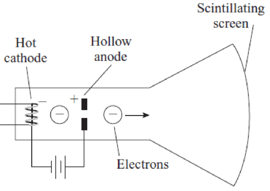
- Watch this video, and devise a rule for the direction of the force
 that the magnet exerts on the moving electrons relative to the direction of their velocity
  and the direction of the magnetic field produced by the magnet. Make sure your rule encompasses all the different scenarios you observe in the video.
 - Compare the rule that you just devised to the right-hand rule for the magnetic force devised earlier. How are they the same and how are they different?
- Your friend says that the beam of electrons is deflected by the magnet because the electrons are charged particles and the magnet is made of iron. How can you convince your friend that they are mistaken?
VIII. Observational experiment to find a pattern in the magnitude of the force exerted by the magnetic field on a moving charged particle
The table below provides data concerning the magnitude of the magnetic force exerted on a moving charged particle by a magnetic field as the following quantities are changed: (1) the particle’s speed, (2) the magnitude of the magnetic field, and (3) the direction of the particle velocity relative to the magnetic field.
| Magnitude of the magnetic field (T) | Charge of the moving particle (C) | Speed v of the moving particle (m/s) | Angle between the velocity and the field | Magnitude of the magnetic force exerted on the particle  (N) (N) |
|---|---|---|---|---|
| B | q | v | 90° | F |
| 2B | q | v | 90° | 2F |
| 3B | q | v | 90° | 3F |
| B | 2q | v | 90° | 2F |
| B | 3q | v | 90° | 3F |
| B | q | 2v | 90° | 2F |
| B | q | 3v | 90° | 3F |
| B | q | v | 0° | 0 |
| B | q | v | 30° | 0.5F |
| B | q | v | 90° | F |
Devise a rule relating the magnitude of the force to these quantities.
